First, check to make sure your repair kit is complete. See component list above.
Door Panel Removal:
(This tutorial was performed on a 2010 E250 van. Other years and versions may vary.)
Photo 1 shows the drivers front door panel.
Note: Every effort is made to accurately portray the installation
process. However, sometimes the vehicle manufacturer makes changes that
affect the steps in door panel removal or installing our product. Use
this tutorial as a guide only. If you are not certain of your ability,
refer installation to a professional.
Work carefully and take notes or make sketches to help you put the door back together properly.
Use a small tray to store screws and parts removed so they don't get lost.
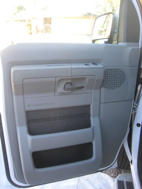 Photo 1
Photo 2
Remove the upper trim panel on the inside corner of the door. It is held with a snap clip. Remove by pulling straight out away from the door.
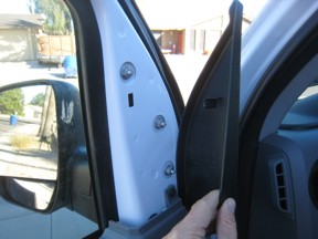 Photo 2
 Photo 3
Remove the screw holding the door panel in place.
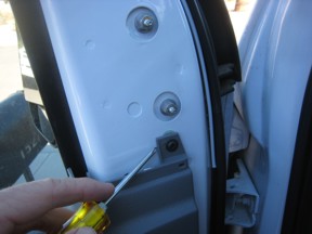 Photo 3
 Photo 4
Remove the plastic screw cover behind the inside door handle. It is a snap in cover. Use a small, flat screwdriver to pry it out carefully.
Remove the door panel holding screw hidden behind the cover.
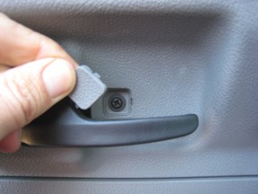 Photo 4
 Photo 5
Remove the round screw cover at the bottom outside corner of the door panel by prying it outward.
There is also a door panel holding screw behind the cover. Remove it now.
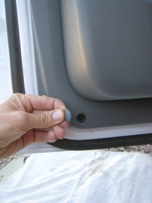 Photo 5
 Photo 6
Carefully pry the switch panel up. It is held in place with two snap clips, one at each end. Gently pry upward on the short ends until the panel comes up.
This is a good time to make sure the window is up, before disconnecting the switch pad.
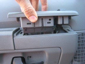 Photo 6
 Photo 7
Disconnect the door lock and power window connectors.
Work carefully. There is a release lever you must push to pull the connectors out. Push the lever in firmly, then pull the connector straight out.
NEVER pull on the wires, hold the body of the connector! DO NOT stick a screwdriver in the connector, there are live connections in there and you can damage your electrical system or yourself!
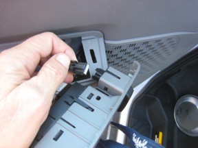 Photo 7
 Photo 8
Connectors come out rather easily when the release lever is depressed. You can see the release lever on the connector to the left, in the center of the body.
Remove the switch module from the door.
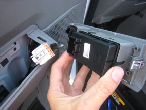 Photo 8
 Photo 9
Remove the inside door handle shroud by prying gently outward. (Screw from photo 4 must be removed first.)
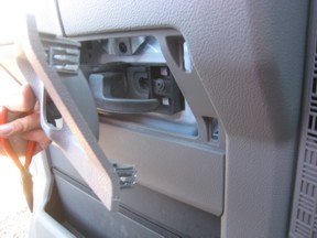 Photo 9
Photo 10
Remove the door panel holding screw located above the handle.
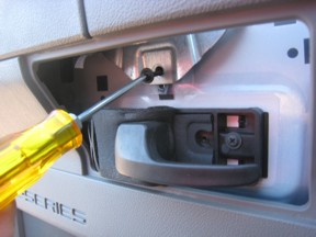 Photo 10
 Photo 11
The door panel should now feel loose. You should be able to lift it upward easily now.
If the panel is not loose, look for additional screws holding the panel in place. Do not force anything as the plastic will break. Look for snap clips or screws on older model years.
Once the panel is loose, lift upward and away from door far enough to disconnect any additional wires such as courtesy lights or mirror controls (shown here, back of panel view.)
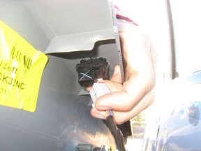 Photo 11
 Photo 12
With the door panel loose, and all wires disconnected, lift the panel up and away from the door frame.
Set the panel off to the side where it can't get damaged.
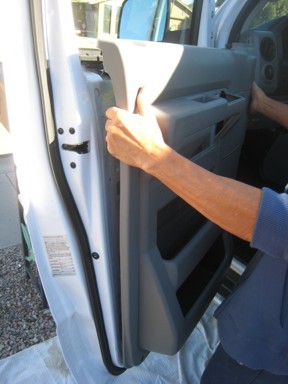 Photo 12
 Photo 13
Peel back the plastic splash guard far enough to allow access to the inner door cavity.
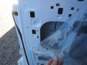 Photo 13
 Steps 14 and 15 are optional, but will give you more room to work.
Photo 14
Note the location and position of the bolt holding the window channel in place. Next, look up in the door cavity and see how the window channel is clipped to the upper window channel with a simple slide on snap clip.
Remove the bolt holding the window channel at the bottom. The window channel will now be loose and can be moved. The window will not move.
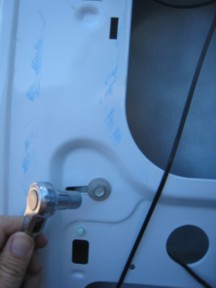 Photo 14
 Photo 15
You can either swing the window channel out of the way, or pull it downward to remove it completely. It is easy to put back on, just note how it is fastened on the upper end before removing it.
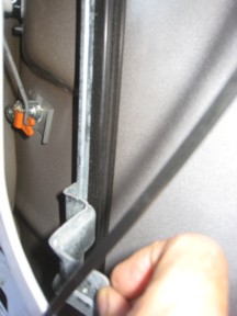 Photo 15
Photo 16
Disconnect the lock rod from the lock pawl. (The lock pawl is the orange piece in this photo.)
Trick: Use a small screwdriver on the end of the lock pawl to separate the snap halves. Push the screwdriver in against the rod, then pull the rod outward against the screwdriver. Both should come out easily without damaging the pawl.
If the door sheet metal is damaged, and you don't plan to have it professionally fixed, straighten out the metal as best you can at this time.
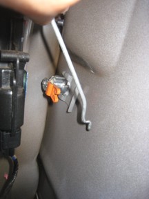 Photo 16
 Now move to the outside of the van.
Align outside repair plate over lock cylinder.
There should be an X marked on the gray side of the plate. Use this mark to ensure you put the plate in the same orientation each time you remove it and put it back on during this process. (If your plate is not marked, make a mark yourself for reference.) You can also place a small mark on the van door for reference. See photo 17.
Center face of lock in large hole in plate, making sure edges of plate are straight.
Use a piece of masking tape to hold plate in place.
 Photo 17
 Photo 18
Carefully mark the center of each corner hole in the repair plate.
The more accurate you can be, the better things will fit.
Make sure the plate is straight! You only get one chance to do this right!!
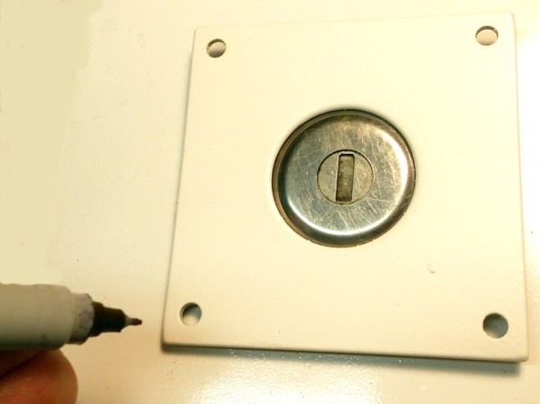 Photo 18
 This is a good time to check, then double check that everything is going to fit both inside and outside of the door.
Photo 19
Once you are convinced everything is ok, use a center punch on each hole center.
Note: The circles drawn around the hole center are for reference only and so you can see the marks in the photos.
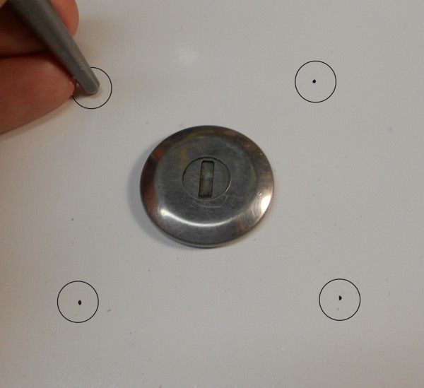 Photo 19
 Photo 20
Use a 9/64" drill bit to drill each hole.
IMPORTANT: Do not use a larger bit or the holes may show from behind the repair plate!
Check and double check all alignment before drilling!
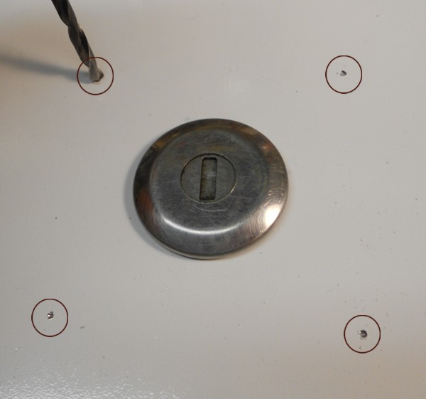 Photo 20
 Move back to inside the door cavity
Photo 21
The lock cylinder is held in the door metal using a snap clip. If your van has already been burglarized, this clip may be at the bottom of the door cavity, and the lock may be hanging out of the door, or missing altogether.
If the clip is still in place, pull it off the lock by sliding it against the door metal, away from the open end of the clip.
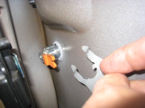 Photo 21
 Photo 22
Use a larger drill bit to deburr the holes you drilled.
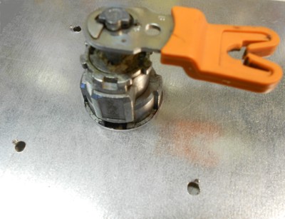 Photo 22
 The other flat plate in the kit is for the inside of the door.
The lock pawl has been removed for this photo, you can leave it in place.
Photo 23
Put the support plate over the lock cylinder. It will need to go around the raised area of the door metal surrounding the lock cylinder.
Mark the inside door metal with an X that corresponds to the X corner on the outside plate.
The inside plate should also be marked with an X in one corner. Align the inside and outside plates so the X marks are on the same corner. The X on each plate goes against the door metal.
Insert the longer screws from the kit from the outside, through the van door metal and through the inside plate.
If needed, make sure the damaged door metal is straightened so plate rests level against the door.
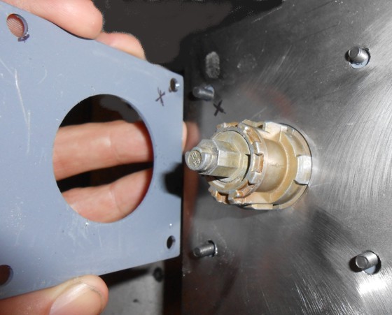 Photo 23
 The lock pawl has been removed for this photo. You can leave it in place.
Photo 24
Put nuts only on the two screws nearest the door jamb.
(Left side of this photo, see Photo 25 to see the nuts in place..)
Back the other two screws out so they do not protrude through the plate.
This allows the security clip to slide on from the side.
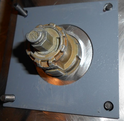 Photo 24
 Prepare to install the security clip by first removing each set screw and applying a drop of thread lock adhesive to each screw.
Put the screws back in the clip, but make sure the threaded end does not come through the security clip on the bottom side.
Photo 25
Slide the security clip open end around the lock body. The plate slides in the grooves on the lock body that the factory snap clip used to hold the lock in the door.
Push the security clip all the way until the closed end of the cutout hits the lock body.
 Photo 25
 Tighten all three set screws just snug. Do not over tighten.
Photo 26
Push the other two outside screws through the inside plate, then put the nuts on and tighten snug.
Test the lock is solid in the door. It should not move at all.
Test the operation of the lock using the key.
Put the lock rod back in place in the lock pawl and test that there is no interference between the rod end and the Jimmi' Jammer clip.
Now you can reassemble your door in reverse order.
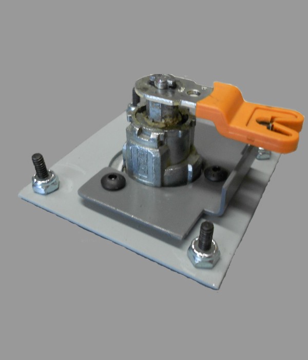 Photo 26
 Place the window warning label in the lower corner of the window, inside surface. Clean and dry the window before putting the sticker on. Place carefully since the adhesive on the stickers is very strong.
That's it!
If you had variations in your installation, please report them to us. Photos are always appreciated, with a brief explanation. We can add it to this tutorial to help others.

All images and descriptions are property of Redline Technical Group, Inc.
Do not use without permission. ©1998 - current